For B.pad
- In B.pad, controller parts are only for USB only. If you want PS/2 connector, don’t solder ZD1, ZD2.
But when you connect through PS/2, you can’t use BootMapper Client tool.
For X2
For B.87, B.face, B.thumb, B.mini
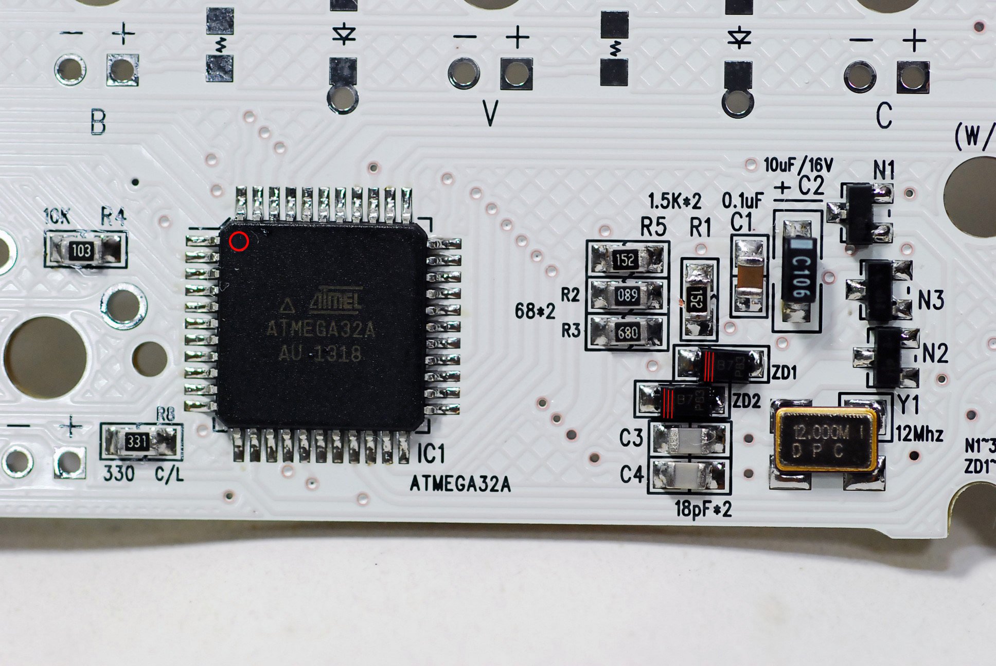
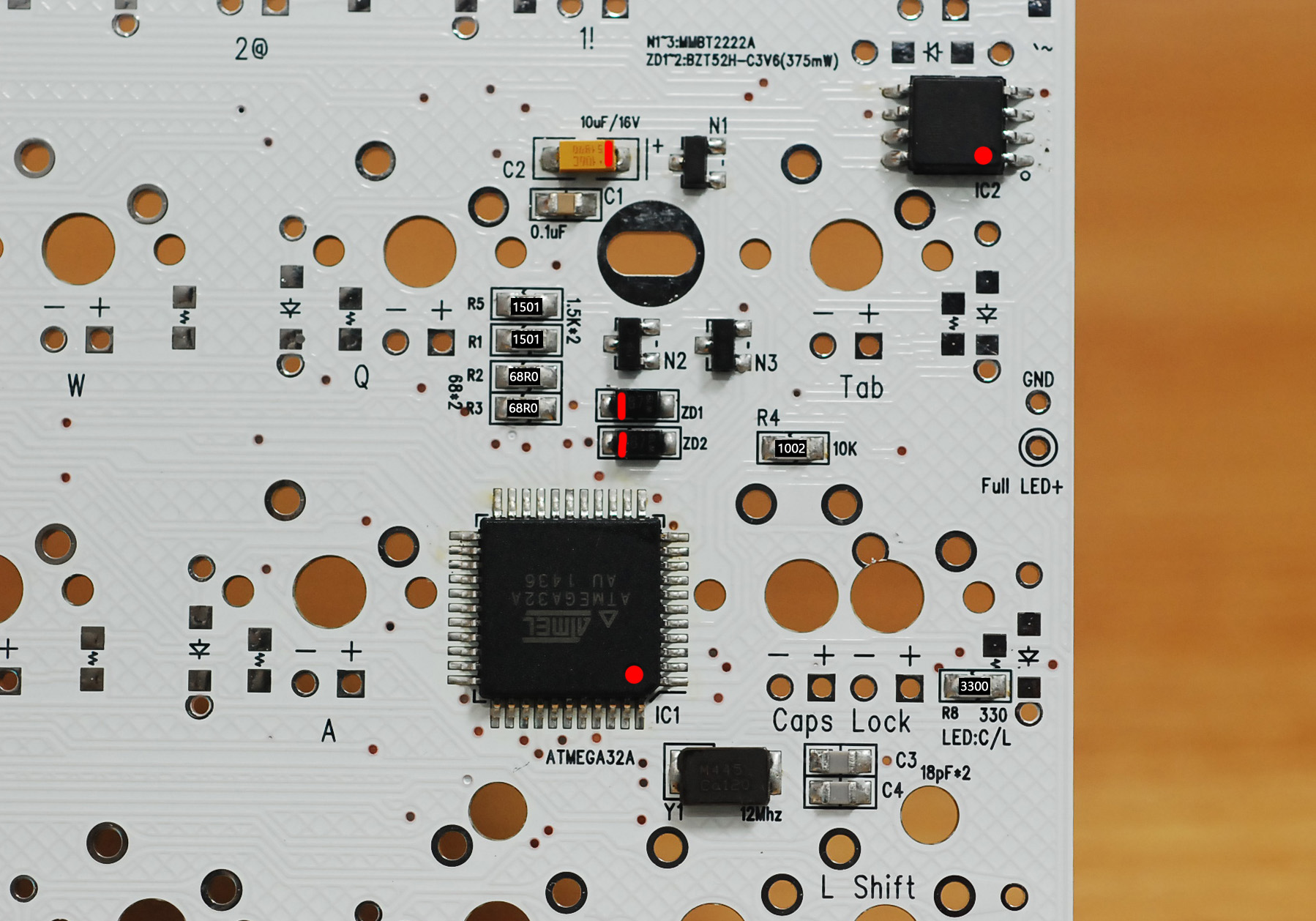
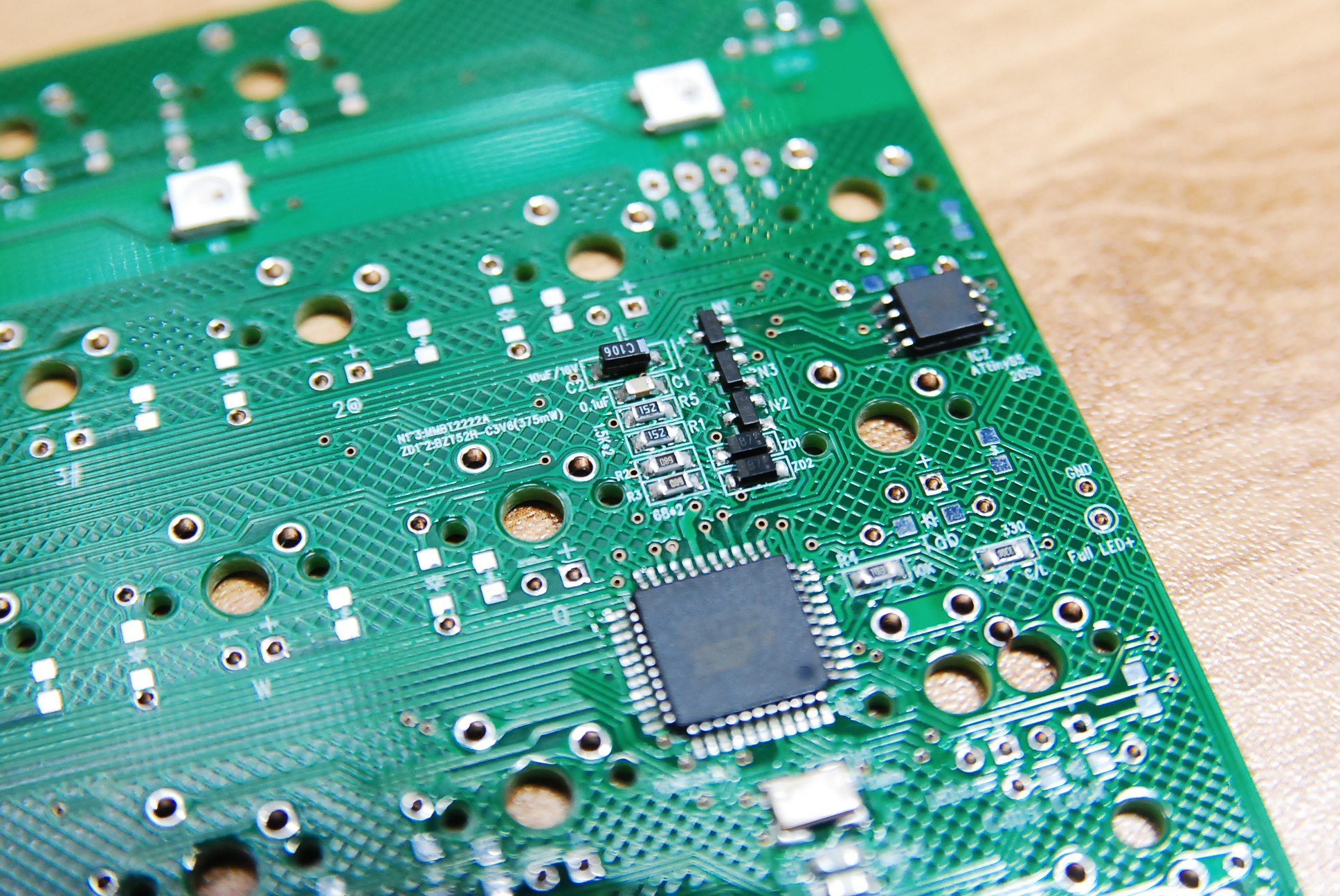
- Resistors for controller parts shoud be soldered like the pic above. There is no direction for the resistor. Number on a resistor means resistor’s value.
- Capacitor “C2” has the directions, so solder it like the pics.
And other parts are going same way as the pics.
- You have to keep in mind that C1 is dark brown and C3/4 are light gray.
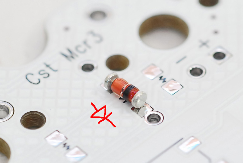
- Crystal(Y1) has no direction, but avoid upside down.
- Transistors (N1~3) are going like the pics.
- MCU(IC1) has the directions.
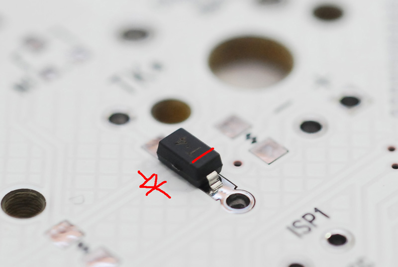
- Zenodiode(ZD1~2) has the direction. Please refer to the pics.
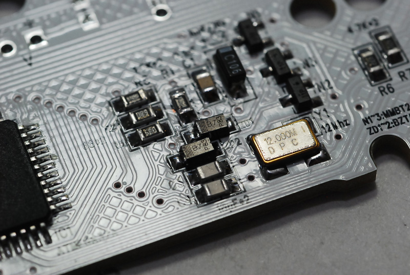
최근 크리스탈(Y1)이 4접점에서 2접점으로 변경되어 아래 사진과 같이 납땜을 해주면 됩니다.
- 네 접점 중 네모 박스 친 부분과 그 대각선을 납땜 해주면 됩니다.


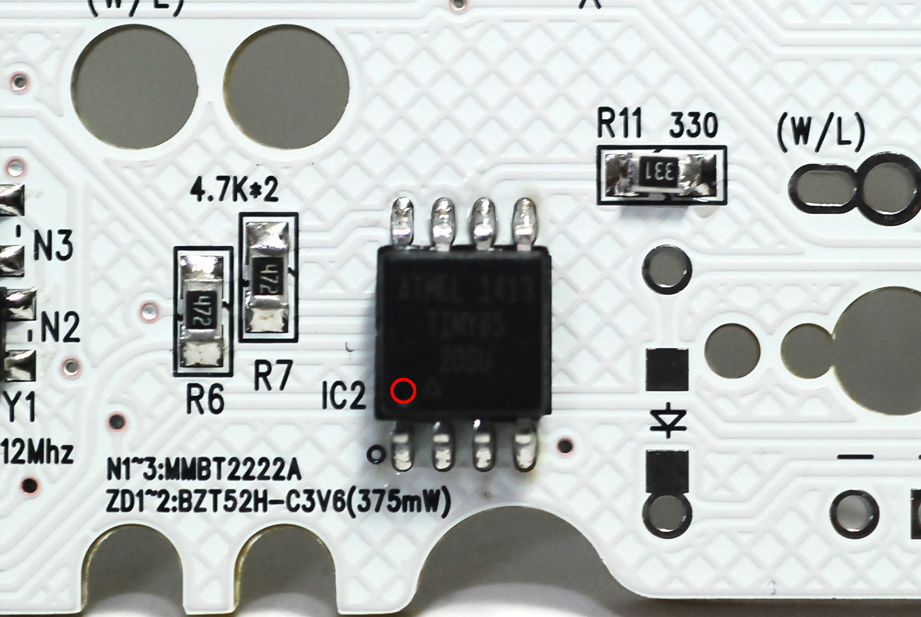
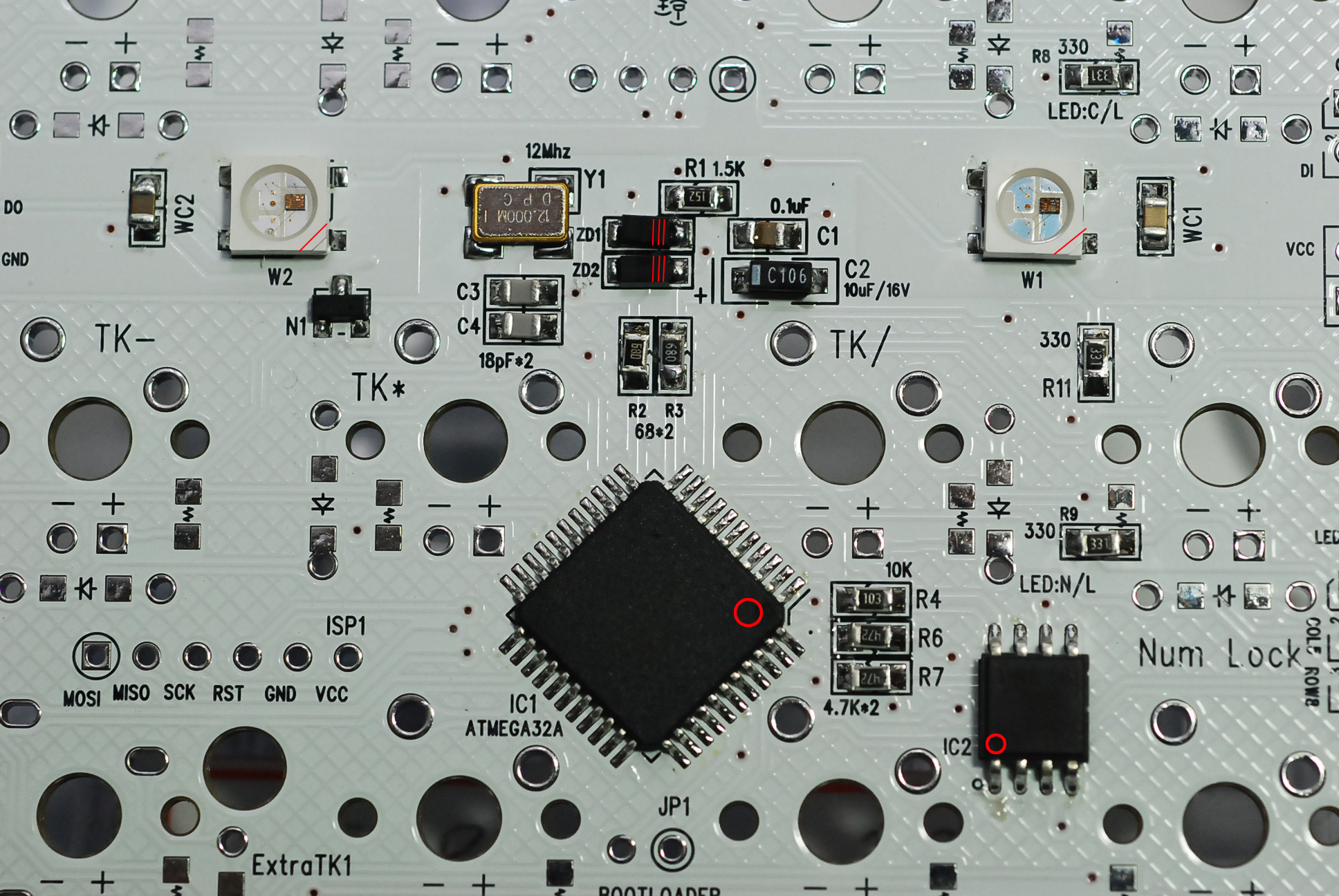
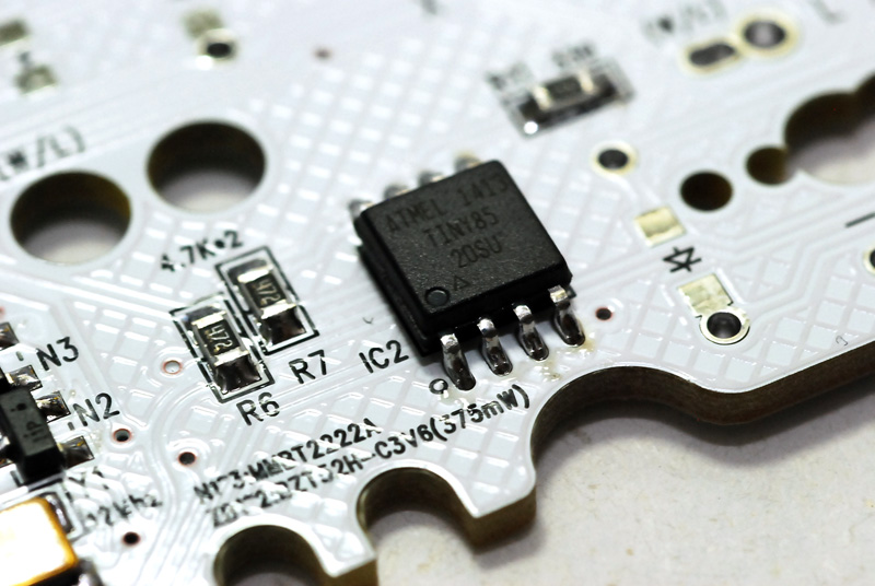
- The pic above shows the RGB LED controller parts.
- Resistors have no direction, but IC2 has.
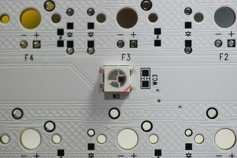
- RGB LED has the direction. On the pcb and RGB LED, you can find a diagonal line at the corner which shows RGB LED direction.
- WC1, WC2, …. mean the capacitory. You can ignore them.
- Diodes have the direction. You can tell them by the black line.
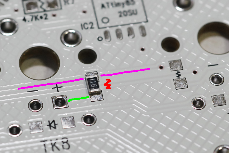
- Resistors for full LED have no direction. Just solder them at the place with resistor mark(red zigzag line)
- Purple line means the power line. Green line is showing the line to the LED.
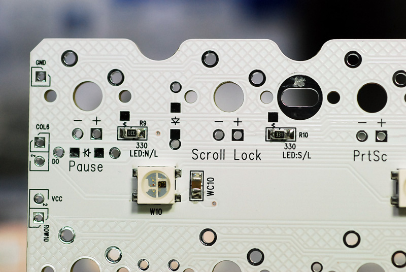
- You can use Scroll Lock and Num Lock key as full LED.
- If you solder them like the pic(horizontally), they act as indicators. If vertically, as full LED.
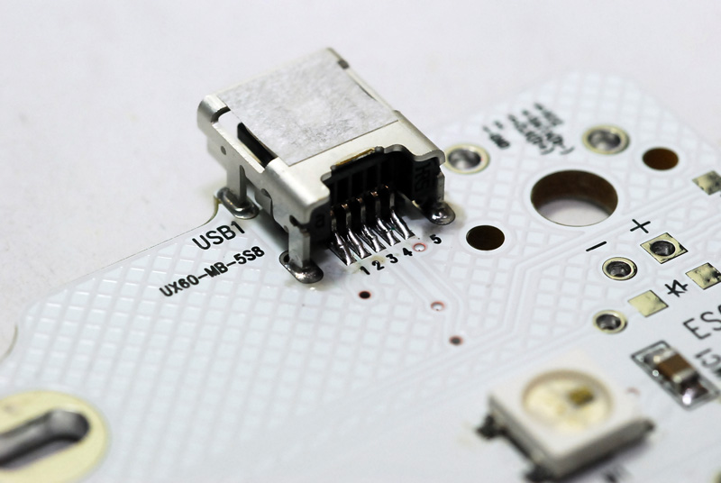
- When you soldr USB connector, please be careful not to overflow the lead.
When you have finished soldering, you should upload the firmware by using BootMapperClient tool, and set the keymapping and RGB value.